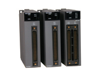
Q75M POSITION MODULED

For applications not needing the advanced features of a motion controller, the QD75 single-slot modules offer the flexibility to include or add motion to Q series control platforms. Features include linear and circular interpolation as well as multi-axis point-to-point commands. The QD75 modules are capable of 1,2, or 4 axis of control. The QD75-M type modules add the functionality and convenience of Mitsubishi’s high-performance Servo System Control Network (SSCNET). All of the QD75 modules are supported by easy to use Windows based programming packages.

QD75MH Positioning Modules for QH Series Automation Platform

One of Q Series’ strengths is the ability to integrate motion control directly onto your system. If a Q Series motion CPU is not required the QD75MH positioning modules provide a range of alternative motion control capabilities. The QD75MH is connected to MR-J3-B Safety servo amplifiers by means of the Servo System Control Network (SSCNET III). This allows compatibility with absolute position systems, between the QD75MH and servo amplifiers (overall distance of 30 meters). Key features include: one, two and four axis versions available; 1MHz output capacity; Support up to 256 axes; 4 axis linear interpolation; Circular interpolation; variety of control schemes (point to point, fixed feed, speed, speed/position & position/speed).

System Configuration

QD75MH Parts List

Model Number

Description

Stocked Item

QD75MH1

SSCNET III Single axis motion controller for Q Series Automation Platform

S

QD75MH2

SSCNET III Dual axis motion controller for Q Series Automation Platform

S

QD75MH4

SSCNET III 4 axis motion controller for Q Series Automation Platform

S

GX-CONFIG-QP-C1

Programming software for QD75M and QD75MH motion modules

S

MR-HDP01

Optional manual pulse generator

S

Cables and Accessories

A6CON1

Spare I/O connector, solder type

S

A6CON2

Spare I/O connector, crimp type

S

A6CON3

Spare I/O connector, IDC type

S

A6CON4

Spare I/O connector, low profile type

-

QD75MCBL-2M

I/O cable - pigtail (order 2 for QD75M4 or QD75MH4) 2M

S

QD75MCBL-5M

I/O cable - pigtail (order 2 for QD75M4 or QD75MH4) 5M

S

QD75MCBL-10M

I/O cable - pigtail (order 2 for QD75M4 or QD75MH4) 10M

S

MR-J3BUS015M

SSCNET III (plastic) cable (QD75MH to MR-J3-BS) and (MR-J3-BS to MR-J3-BS) 0.15M

S

MR-J3BUS03M

SSCNET III (plastic) cable (QD75MH to MR-J3-BS) and (MR-J3-BS to MR-J3-BS) 0.3M

S

MR-J3BUS05M

SSCNET III (plastic) cable (QD75MH to MR-J3-BS) and (MR-J3-BS to MR-J3-BS) 0.5M

S

MR-J3BUS1M

SSCNET III (plastic) cable (QD75MH to MR-J3-BS) and (MR-J3-BS to MR-J3-BS) 1M

S

MR-J3BUS3M

SSCNET III (plastic) cable (QD75MH to MR-J3-BS) and (MR-J3-BS to MR-J3-BS) 3M

S

MR-J3BUS5M-A

SSCNET III (plastic) cable (QD75MH to MR-J3-BS) and (MR-J3-BS to MR-J3-BS) 5M

S

MR-J3BUS10M-A

SSCNET III (plastic) cable (QD75MH to MR-J3-BS) and (MR-J3-BS to MR-J3-BS) 10M

S

MR-J3BUS20M-A

SSCNET III (plastic) cable (QD75MH to MR-J3-BS) and (MR-J3-BS to MR-J3-BS) 20M

S

MR-J3BUS30M-B

SSCNET III (glass) cable (QD75MH to MR-J3-BS) and (MR-J3-BS to MR-J3-BS) 30M

S

MR-J3BUS40M-B

SSCNET III (glass) cable (QD75MH to MR-J3-BS) and (MR-J3-BS to MR-J3-BS) 40M

-

MR-J3BUS50M-B

SSCNET III (glass) cable (QD75MH to MR-J3-BS) and (MR-J3-BS to MR-J3-BS) 50M

-

Manuals

IB(NA)66900

GX-CONFIG-QP-C1 software operating manual

-

IB(NA)0300117

QD75MH user manual (details)

-

IB(NA)0300099

QD75MH user manual (hardware)

-

Note: Please refer to the Servomotor and Amplifiers Section in this Product Selection Guide to select servo amplifier and motor model numbers.

QD75MH Performance Specifications

Model Number

QD75MH1

QD75MH2

QD75MH4

No. of Control Axes

1 Axis

2 Axis

4 Axis

Interpolation Function

None

2-axis linear interpolation 2-axis circular interpolation

2-, 3-, or 4-axis linear interpolation; 2-axis circular interpolation

Control System

PTP (Point To Point) control, path control (both linear and arc can be set), speed control, speed position switching control, position-speed switching control

Control Unit

mm, inch, degree, PLS

Positioning Data

600 data (positioning data Nos. 1 to 600)/axis (Can be set with peripheral device or PLC program.)

Backup

Parameters, positioning data, and block start data can be saved on flash ROM (battery-less backup)

Positioning

Positioning System

PTP control: Incremental system/absolute system; Speed-position switching control: Incremental system/absolute system (*1); Position-speed switching control: Incremental system; Path control: Incremental system/absolute system

In Absolute System

-214748364.8 to 214748364.7 (µm) • -21474.83648 to 21474.83647 (inch) • 0 to 359.99999 (degree) • -2147483648 to 2147483647 (PLS)

In incremental System

-214748364.8 to 214748364.7 (µm) • -21474.83648 to 21474.83647 (inch) • -21474.83648 to 21474.83647 (degree) • -2147483648 to 2147483647 (PLS)

In Speed-Position Switching Control (INC mode) / Position-Speed Switching Control

0 to 214748364.7 (µm) • 0 to 21474.83647 (inch) • 0 to 21474.83647 (degree) • 0 to 2147483647 (PLS)

In Speed-Position Switching Control (ABS Mode) (*1) Positioning Range

0 to 359.99999 (degree)

Speed Command

0.01 to 20000000.00 (mm/min) • 0.001 to 2000000.000 (inch/min) • 0.001 to 2000000.000 (degree/min) (*3) • 1 to 50000000 (PLS/s)

Acceleration/ Deceleration Process

Automatic trapezoidal acceleration/deceleration, S-pattern acceleration/deceleration

Acceleration/ Deceleration Time

1 to 8388608 (ms): Four patterns can be set for each of acceleration time and deceleration time

Sudden Stop Deceleration Time

1 to 8388608 (ms)

Starting Time (ms) (*2)

1-axis linear control: 3.5

Factors in starting time extension. The following times will be added to the starting time in the described conditions:

  • S-pattern acceleration/deceleration is selected: 0.5
  • Other axis is in operation: 1.5
  • During continuous positioning control: 0.2
  • During continuous path control: 1.0

1-axis speed control: 3.5

2-axis linear interpolation control (Composite speed): 4.0

2-axis linear interpolation control (Reference axis speed): 4.0

2-axis circular interpolation control: 4.0

2-axis speed control: 3.5

3-axis linear interpolation control (Composite speed): 4.0

3-axis linear interpolation control (Reference axis speed): 4.0

3-axis speed control: 3.5

4-axis linear interpolation control: 4.0

4-axis speed control: 4.0

External Wiring Connection System

40-pin connector

Applicable Wire Size

0.3 mm² (when A6CON1 and A6CON4 are used), AWG#24 to 28 (when A6CON2 is used), AWG#28 (twisted)/AWG#30 (single wire) (when A6CON3 is used)

Applicable Connector for External Device

A6CON1, A6CON2, A6CON3, A6CON4 (sold separately)

SSCNET III Cable

MR-J3BUS_ _M (*4)

  • Connection between QD75MH and MR-J3-_ _B Safety.
  • Connection between MR-J3-_ _B Safety and MR-J3-_ _B Safety.
  • Standard code for inside panel.
  • 0.15m (0.49ft.), 0.3m (0.98ft.), 0.5m (1.64ft.), 1m (3.28ft.), 3m (9.84ft.)

MR-J3BUS_ _M-A (*4)

  • Connection between QD75MH and MR-J3-B Safety.
  • Connection between MR-J3-_ _B Safety and MR-J3-_ _B Safety.
  • Standard code for outside panel.
  • 5m(16.40ft.), 10m (32.81ft.), 20m (65.62ft.)

MR-J3BUS_ _M-B (*4)

  • Connection between QD75MH and MR-J3-_ _B Safety.
  • Connection between MR-J3-_ _B Safety and MR-J3-_ _B Safety.
  • Long distance cable.
  • 30m (98.43ft.), 40m (131.23ft.), 50m (164.04ft.)

SSCNET III Cable Overall Length (m)

50

50

50

Internal Current Consumption (5VDC)

QD75MH1 : 0.60A

QD75MH2 : 0.60A

QD75MH4 : 0.60A

Flash ROM Write Count

Max. 100000 times

No. of Occupied I/O Points (Points)

32 (I/O assignment: 32 points for intelligent function module)

Dimensions (mm (inch)) H x W x D

98 x 27.4 x 90 (3.86 x 1.08 x 3.54)

Weight kg (lbs)

0.15 (0.33)

Notes:

  1. In speed-position switching control (ABS mode), the control unit available is “degree” only. (For details, refer to “Section 9.2.17 Speed position switching control (ABS mode)”.)
  2. Using the “Pre-reading start function”, the virtual start time can be shortened. (For details, refer to “Section 12.7.8 Pre-reading start function”.)
  3. When “Speed control 10 x multiplier setting for degree axis function” is valid, this will be the setting range 0.01 to 20000000.00 (degree/min).
  4. _ _ = Cable length. (015: 0.15m (0.49ft.), 03: 0.3m (0.98ft.), 05: 0.5m (1.64ft.), 1: 1m (3.28ft.), 3: 3m (9.84ft.), 5: 5m (16.40ft.), 10: 10m (32.80ft.), 20: 20m (65.62ft.), 30: 30m (98.43ft.), 40: 40m (131.23ft.), 50: 50m (164.04ft.) )

QD75MH Input/Output (X/Y) Comparisons

Input (X)

Name

QD75MH_

(QD75) READY

X00

Axis 1 Start Complete

X10

Axis 2 Start Complete

X11

Axis 3 Start Complete

X12

Axis 4 Start Complete

X13

Axis 1 BUSY

X0C

Axis 2 BUSY

X0D

Axis 3 BUSY

X0E

Axis 4 BUSY

X0F

Axis 1 Positioning Complete

X14

Axis 2 Positioning Complete

X15

Axis 3 Positioning Complete

X16

Axis 4 Positioning Complete

X17

Axis 1 Error Detection

X08

Axis 2 Error Detection

X09

Axis 3 Error Detection

X0A

Axis 4 Error Detection

X0B

Axis 1 M Code ON

X04

Axis 2 M Code ON

X05

Axis 3 M Code ON

X06

Axis 4 M Code ON

X07

Synchronization Flag

X01

Use Prohibited

X02, X03, X18 to X1F

Output (Y)

Name

QD75MH_

Axis 1 Positioning Start

Y10

Axis 2 Positioning Start

Y11

Axis 3 Positioning Start

Y12

Axis 4 Positioning Start

Y13

Axis 1 STOP

Y04

Axis 2 STOP

Y05

Axis 3 STOP

Y06

Axis 4 STOP

Y07

All Axis Servo ON

Y01

Axis 1 Forward Run JOG Start

Y08

Axis 1 Reverse Run JOG Start

Y09

Axis 2 Forward Run JOG Start

Y0A

Axis 2 Reverse Run JOG Start

Y0B

Axis 3 Forward Run JOG Start

Y0C

Axis 3 Reverse Run JOG Start

Y0D

Axis 4 Forward Run JOG Start

Y0E

Axis 4 Reverse Run JOG Start

Y0F

PLC READY

Y00

Axis 1 Execution Prohibition Flag

Y14

Axis 2 Execution Prohibition Flag

Y15

Axis 3 Execution Prohibition Flag

Y16

Axis 4 Execution Prohibition Flag

Y17

Use Prohibited